Thursday, October 27, 2011

Final Schematic Design

As I was changing my conceptual model and try to evolve it into a newer shape, I came up with my final schematic model design. The Model has taken some of ideas from with the connectivity conceptual model and  has some similarities to it. At this point, I started to locate my model in my final topography and understand the density of the building and it reads in the site.

Final Concept Schematic Model


After I finished working in my model, I started working with my first functional adjacencies  from my program report and my my functional adjacencies plan from my first iteration. At this point, I started to create the schematic floor plans with the new final schematic building shape. The building is three stories high, and I started the production of the elevations of the buildings and the section.

First Level Floor Schematic Plan

Second Level Floor Schematic Plan

Third Level Floor Schematic Plan

North Schematic Elevation

East Schematic Elevation

West Schematic Elevation

South Schematic Elevation

Schematic Section

Finally, I located the building in the front in order to understand how dominant the building is and what are the best option for the building orientation, and how the view to the falls river could be taken advantage as much as possible.


First Iteration with Site Analysis

In our first iteration, the objective was to show a site analysis. At this point, a concept design was needed to be selected and implemented into the site. In my first attempt, I chose the same concept that I had been working on, which was the concept from lighting and shadow. The topography of the site helped me understand that the site is basically flat but that has a steep slope in the front where the stores are located. In addition to the site analysis, it was clear to understand how the traffic patterns moved, these patterns are the vehicular and pedestrian traffic patterns, depending on the time of the day the street will be busier and could bring clientele to the spa. Also, the idea of the building orientation in order to understand which is the proper location to the building since it is important to take advantage of natural lighting to be sustainable as much as possible. Finally, the criteria of aesthetics and the views of how the building could take advantage of the Falls River so that in can bring the attention of their customers and captivate them through the attractiveness of the facility, and its views.
Site Analysis

First Level and Site Analysis Plan 

Second Level and Site Analysis Plan

Schematic Model and Topography


After our project reviews and how the project was progressing, the conceptual idea became too simplistic and it was necessary to take another direction with another concept model. For this reason, the concept model I started working was my connectivity concept model. 

Connectivity Concept Model

As I was working throughout to come up with another schematic design that was not too simplistic, I used the fraction cut technique to cut a section of my Connectivity Section Model and create another concept design. 

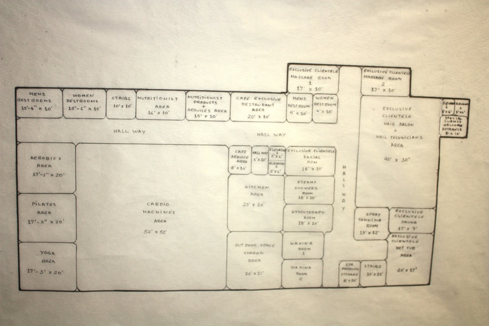
 Once this evolution was changing, I used my functional adjacencies diagram to start the production of my final schematic design.  

Wednesday, October 26, 2011

Schematic Package

In the schematic package, the idea was to implement one of our concept designs and use our functional adjacencies diagram from our program report to make a complete package that included floor plans, elevations. In my case, I selected my concept design that focused on natural lighting and shadow. I worked with my functional adjacencies diagram to make it work according to my concept design.
 First Level Floor Plan

Second Level Floor Plan


 North Elevation


South Elevation


East Elevation

West Elevation